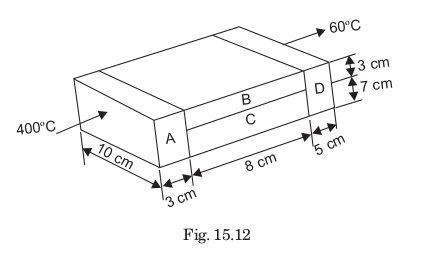
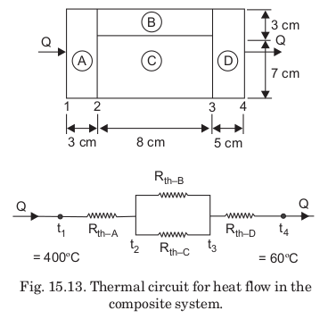
The thermal circuit for heat flow in the given composite system (shown in Fig. 15.12) has been illustrated in Fig. 15.13.
Thickness :
LA=3cm=0.03mLB=LC=8cm=0.08mLD=5cm=0.05m
Areas :
AA=0.1×0.1=0.01m2AB=0.1×0.03=0.003m2AC=0.1×0.07=0.007m2AD=0.1×0.1=0.01m2
Heat flow rate, Q :
The thermal resistances are given by
Rth−A=kAAALA=150×0.010.03=0.02Rth−B=kBABLB=30×0.0030.08=0.89Rth−C=kCACLC=65×0.0070.08=0.176Rth−D=kDADLD=50×0.010.05=0.1
The equivalent thermal resistance for the parallel thermal resistances Rth–B and Rth–C is given by:
(Rth)eq.1=Rth−B1+Rth−C1=0.891+0.1761=6.805(Rth)eq.=6.8051=0.147
Now, the total thermal resistance is given by
(Rth)total=Rth−A+(Rth)eq.+Rth−D=0.02+0.147+0.1=0.267Q=(Rth)total(∆t)overall=0.267400−60=1273.4W

